turning radius

I needed to figure out if my design will make all the turns on the DLR line.

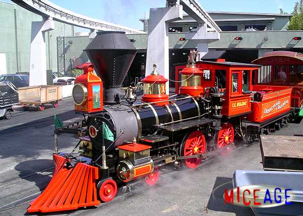
A discussion on Burnsland figured out that the sharpest curve on the DLR main line is 278′. But the absolute sharpest turn is actually at the roundhouse switching track. Here’s the #1 on this track entering the main line on one morning.

I don’t know what that particular radius is, but just for fun I assumed that it’s half of the smallest turn on the mainline, or 139′.

Figuring out the turning radius for a vehicle is actually not a completely straightforward task. A lot of different geometries can define the final turning radius. Since I’m just doing a verification of my own design, I just made up a fairly simple one.

Since there are 4 wheels on each rail, when going around a curve, each wheel can be approximated as a point on a curve. Connecting these points describes an arc, which we can then get its radius.

There is “play” with these points also because the wheels have thickness to them. (Technically, the driver wheels cannot deflect because they are rigid in the frames). In the above picture, I deflected the pilot truck until the rear wheel is near but not in contact with the inner crosshead guide. Then I draw an arc connecting the 4 wheels together.

This process gives an arc of about 1350″, or 112′, which is less than my assumed smallest curve of 139′, and certainly much less than 278′ on the mainline.

So indeed, there’s plenty of room for the pilot truck to turn. Generally, rail curves are made to be as large as possible, so in reality the pilot truck does not swing that much.

24: boiler and firebox

Making the boiler is a bit like a mini-project in itself. It consists of several major parts including:

  • The firebox
  • The stay bolts
  • The tubes and sheet; and
  • The steam dome

Here, I’ve made the first two. The firebox is fitted in the boiler with adequate (3″) water space on all sides. The firebox is also fixed to the boiler by almost 350 stay bolts.

The stay bolts are 7/8″ diameter and vary in length depending on the location. The bolts are supposed to be threaded at both ends as the method of fastening but that detail is not shown nor necessary for this purpose. One other neat feature is that the outer end of the bolts have a 3/16″ diameter hole drilled 1.25″ deep. This is supposed to leak water to alert the crew if the bolt has fractured.

Here’s a picture of the real stay bolt ends.

Now, getting information on the Disney boiler may seem nearly impossible. Fortunately, they have a spare! Better yet, they’ve cut it open.

After the major Ripley’s refurb which includes it getting a new boiler, the roundhouse crew decided to keep the old boiler and dissected it. They keep it in the back of the roundhouse to teach new engineers the inner workings of steam boilers. Here’s a picture of it I took at one of the visits. I wonder if it’s still there.

By the way, the plywood sheathing you see behind the boiler is not a wall–that was the coach Lilly Belle!

Anyway, the boiler I made is basically the same. It’s missing the tubes and tube sheet, steam dome, fire brick lining, and a cutout for the atomizer, blowout, and louvers.

The CK Holliday was meant to be a model of a wood burner. At the park, she burns oil (diesel, actually), so the firebox will not get the firebox grating that would be for wood burning engines. But even as the bottom is closed for burning oil, I wonder if there is an opening at the bottom of the firebox for drafting or cleanout? If you look at the engine at night, the glow of the fire is readily seen underneath the firebox. So there is light leaking through… or is that from the atomizer louvers?

EDIT: Some more progress below:

The above shows addition of the tubes and tube sheet. There is also a flange at the steam dome opening. The steam dome will be welded to this flange.

The tube sheet still needs to be punched in for the dry pipe.

The tubes or flues are 2″ O.D. with 3/16″ wall thickness. There are 67 tubes giving total area of 138.95 sq. in.

23: taking shape

Just for fun, I added the rough boiler to the frame to see how the proportions are turning out. I gotta say, just adding the tube really gives the whole project some life!

Other than the saddles, there’s no “physical” way for the boiler to connect to the frames yet (that’ll be the job of the braces). So right now it’s just “hanging” there.

Notice also that the firebox is inside the boiler now, but it’s not yet connected by rivets and stay bolts.

22: boiler

With the engine’s frame completed, it’s now ready to support the heart of the engine: the boiler!

The dimensions were taken from original drawing. Although the CK Holliday’s spec calls it a 32″ diameter boiler, its actual diameter varies a little due to sheet metal thickness and section lapping. Anyway, its norminal diameter is still just that–32″.

The cutaway view shows how sections of the boiler are welded together.

The holes at the top will receive the steam dome and smoke stack.

21: crosshead

The CK Holliday’s crosshead is fairly typical of the period, using a 4-guide rail type. The guide rails are bolted to the rear cylinder cap and the “yoke”, which is the same piece/casting that supports the bottom boiler brace (not the boiler braces on the pilot deck!).

Here are pictures of the crosshead assembly, both real and modeled.

In the above shot, the left crosshead is seen upper left, and the right hand crosshead is lower right.

Here’s the crosshead in its rails with some parts made see-through to better understand how the crosshead is built.

It’s a fairly straightforward part. There’s a center casting with a socket to receive piston rod. The center casting has a cast-in pin that is used to drive the connecting rod. It also has “wings” that are made to ride the guide rails. Fitted between the guide rails and the casting are “gibs” which are thin brass wearing surface.

20: buttoning up the cylinders

With the steam pistons in place in both cylinders, it’s time to button them up, making the saddle/cylinder assembly complete.

Above: both cylinders are closed off with front and rear caps. Note also the driver springs and equalizer system are now in place.

Below shows the right piston (blue) inside the cylinder. The rear cylinder cap is also shown with gland packing detail. The 2 blocks welded on the cap will be used to attach the crosshead guides.

Extra: this view shows the spring and equalizer assembly. Fairly straightforward.

19: steam piston

Time to turn attention to a different component: the steam piston, or, the thing that makes the train go choo-choo.

A relatively straightforward part to model. Since there are, I think, literally no material available on the make-up of the DLRR #1 piston, I had to rely on more traditional sources.

I assume that DLRR uses a built-up piston, the most common type for the period.

The steam piston is made with several parts: the main body called “spider”, the cover plate or “follower”, and the packing.

The spider is simply a casting with 5 points to mount the cover plate. DLRR may have simplified the design to 4 points, but not knowing this for sure, I just go with the traditional design.

The packing consists of a “T” ring and 2 packing rings fitted on the spider. They are supposed to be cast slightly larger than the piston itself. This way, the packing will fit tight against the inside bore of the cylinder. The following cross section shows how the pieces fit together.

Note the notches around the circumference of the packing rings. This allow the rings to expand with heat. The gaps between parts serve the same purposed.

And here’s the piston as a whole, with transparent cover plate so that the spider can be seen.

17: pilot truck swing

The swing casting is finished. With it placed in the assembly, one can see just how exactly the swing casting system works:

[youtube http://www.youtube.com/watch?v=clPFcE4FYKc&w=560&h=315]

Here’s a general overview. The swing casting is connect by 4 links, forming something similar to a “swing set” found on kid’s playgrounds. The casting is highlighted in blue.

The cosmetic components (pins, bolts, etc.) have not been added to the model yet, but the mechanical definitions are there, which make the above animation possible.